August 10, 2018 - Happily, the new version 4 μBITX incorporates a new receive audio system that solves that pesky click. So if you have one of the newer boards then there is no need for this modification. However, if you have one of the older models and one of the kits, read on...
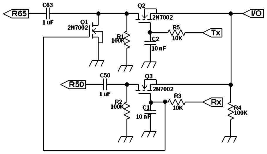
The speaker “click” or “pop” that occurred in the µBITX whenever it transitioned from receive to transmit or back again was solved by Wayne Cheng’s (VA7AT) circuit. The receive and transmit audio preamplifiers are rewired to leave them constantly powered and MOSFET gating circuits are installed to steer the audio without the noise bursts. It has been in use here for several months but several people have avoided building the circuit due to lack of a proper printed circuit board.
Kees Talen, K5BCQ, stepped forward to offer an entire kit. Not only a professional quality board, etched, drilled, and silk screened, but a full kit of parts including header pins and even a piece of double-sided foam tape to mount it! From May to August 2018 he sold and shipped 419 of those kits. They are no longer available. Great job Kees!
All ten parts are Surface Mount Devices. This is the new normal. Even the BITX rigs are SMD. This may be new territory for some of the people building and installing this kit but it should be a good adventure. The µBITX will require some surgery so we cannot avoid surface mount construction if we are to perform this modification. A few tips and explanations can be found elsewhere on this site and can be accessed directly by clicking here.
The new kit includes spaces and solder pads for two of the 1 uF blocking capacitors (C50 and C63) that were “tombstoned” (stood on end) in my original modification. This will allow removal from the µBITX board and re-installation on the new kit board, a much more mechanically robust installation. Plenty of extra ground attachments are provided and the interconnection points are all prepared if the builder wishes to install the provided pin headers so that they can use plugs to make it easily disconnected for replacement or modification.
Note: At the risk of repetition I will briefly describe the building sequence of this kit as I have done for the AGC kit and for installation in the BITX40. Although I do tend to repeat myself unintentionally, this is for the convenience of the builder.
This kit is shipped with all of the components, board, header pins, and foam tape attached to the schematic diagram with adhesive tape next to their parts listing. The surface mount components are in their sections of reel tape and secured by plastic film on the top. If the envelope has been roughly handled then some of these tiny parts may have escaped so when you open the envelope be careful to check for any components rattling around loose.
Remove the printed circuit board and place it in a small vise in a horizontal position. I recommend a vise as low to the work surface as possible. The higher it is placed, the more likely that part that escapes the work area will never be found. Lacking such a vise you can get by with a glob of “poster putty”. The dollar store variety is fine. Just stick a goodly wad on the work surface and embed the circuit board so that it is stable, secure, and flat.
I recommend a temperature controlled iron, 40 to 60 watts, with a small tip. I use .01” diameter solder for surface mount work since it provides superior control of solder quantity. Melt a small amount of solder on one of the pads for R3. Heat it just enough to melt the solder onto the pad but remove the heat before the flux cooks off. The idea is to leave enough for later re-flowing without additional flux.
Releasing the first bit of components at the top of the adhesive tape (two 10K resistors) you will find them attached to their original section of reel tape. Holding them close to the work surface (they bounce!) carefully remove the retaining film and tip them out. Use an ohmmeter to confirm their value and then place the first one in position on the pads for R3. Nudge it into place, centered as much as possible.
Hold the resistor gently in place with the end of a soldering aid, small tweezers, a stainless dental probe or some such, near the center of the part’s body. Apply the soldering tip to the joint at the pad that you previously prepared. When you see the solder melt hold the heat just long enough to give it time to flow onto the resistor and create a bond. Remove the heat and hold the part in place until the solder solidifies. Now pick up the solder and properly solder the other end of R3. Use just enough solder to make a nice fillet, ensuring a secure electrical and mechanical joint. Hold the hot tip on the joint long enough to cook off most of the flux but not so long that the other end of the resistor gets hot enough to melt the solder there and release the part to skate out of position. It’s a balancing act! More art than science. Now return to the first joint and properly solder it.
If the part skids out of place, use stainless steel tweezers to pick it up while alternately heating the connection(s). Use de-soldering braid to remove excess solder from the pads and then re-install. With practice you will develop the proper timing and you will seldom have a part slide out of position.
Next install R5, the remaining 10K resistor, using the same method. The three 100K resistors follow afterward.
The three transistors are MOSFET and are sensitive to electrostatic discharge. Treat them accordingly.
With all ten parts mounted on the board it is time to prepare the µBITX board for the kit. Remove C50 from the µBITX and install it in the provided position on the kit board. This is a non-polarized ceramic capacitor. The new board is labeled in case you replace C50 with a polarized type. Do the same for C63, thus completing the component installation.
Now to re-arrange the preamp power:
Referring to the sketches, locate the receive (RX) power supply trace shown in the main sketch and carefully separate it at the location shown in the expanded sketch of the area (Figure RX). Use a sharp knife to cut across trace. Make a small gap, just enough to ensure that it is open. Carefully scrape the conformal coating from each end of that severed trace to reveal the bare copper conductor. The end that sourced the original receive voltage will be jumpered to the “RX” input on the kit board.
Scrape off the coating over the 12 volt supply trace section adjacent to the other end of the severed trace, the one that leads to R52. Use a small wire clipping to connect the two. This taps the full-time 12 volt supply to R52 and the rest of the receive preamp, keeping it active.
Refer to the sketches and find the transmit (TX) supply trace to R66. I like to take advantage of the through-hole vias that connect to the bottom layer. They make excellent connection points. Cut the TX trace below the “knee” near the short 12 volt supply run. Remove the coating on the end of the severed trace that feeds R66, and around the adjacent 12 volt via. Solder a short wire clipping from the via to the bared trace to R66. If you bend one end of the clipping 90 degrees then it will drop into the via to help hold it in place. Clean the via on the remaining TX trace for connection to the “TX” input to the kit board.
I will leave the option of using plugs and jacks to the individual. I prefer just hard wiring to keep things simple and avoid intermittent connections and to save space. At this point you can install the supplied header pins or just the six jumper wires to the board. Clean off any flux with alcohol or flux remover.
That is a lot of connections for that little board! Looks like a 6-legged spider. I positioned mine with the bottom of the board up next to C52 and C64, those big electrolytics.
That completes installation. Be sure to check your work before applying power. I have not had any issues with my installations and cannot think of any trouble shooting hints. If you find that something doesn’t work, you might start with voltage checks at the RX, TX, and 12 volt points. An oscilloscope would be the best tool to follow the signal through the gating. Without an oscilloscope I would suggest a signal injector like this example.
I hope that you will enjoy the results of this modification as much as I have. If this is your first venture into the world of surface mount electronics I am sure that you will have picked up some considerable skills, too. Perhaps you will be a bit more comfortable working with these tiny parts and are ready to tackle some more of these projects!
de ND6T