Aside from dressing up the display (taking up room is more like it) there is little use for a signal strength indicator (“S” meter) unless it is accurate. Admittedly this implementation is not accurate, merely a nod to the notion. That said, it does work as well as a few “store-bought” rigs that I have used. Since it is simple and easy, I will pass it on for what it's worth.
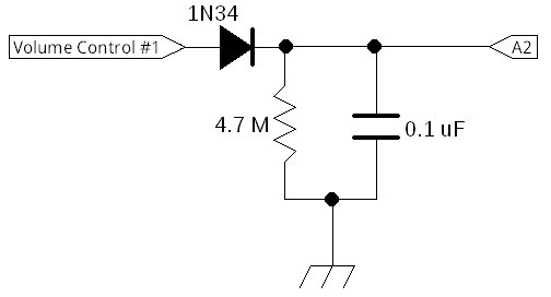
Just three components, none critical. I ran a lead from the “hot” side of the volume control through a diode to an available analog port on the Nano® and paralleled a 0.1uF capacitor with a 4.7 Megohm resistor from that port to ground. The diode can be a silicon switching diode like a 1N914 or 1N4148 but a germanium like a 1N34A will work better for the lower strength levels.
The reason for the inaccuracy is primarily due to lack of the usual AGC circuitry. Normally one just measures the AGC voltage and scales it to suit. This mod is simply using the detected audio and then using a short-period peak hold circuit to feed the micro-controller. If you decide to add any of the AGC projects at this site (like this one then you can implement an exceptionally accurate measurement.
Examples of software implementations can be found in the "Tuning Methods" pages here (EZall.ino) and here (B40all.ino). I avoided a bar-graph display since it is infrequently updated to avoid noise in some installations and since the minimalist 16 character 2 line display quickly runs out of room!
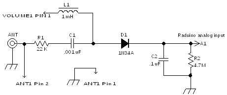
Here’s a method that will allow you to have both a signal strength meter and a rudimentary output power meter and it only needs one Arduino pin! “Rudimentary” because, unlike the Stockton bridge described here, this simple circuit relies upon a good impedance at the test point. However, this can be an advantage! What you really want a power monitor for is to not only see if you are transmitting at the power level that you want but it would be nice to see if something has changed in your antenna system! This gadget will do just that. If you see the power suddenly increase (or decrease) then you can be sure that something is different and you can then pursue it.
A simple 22 kilohm ¼ watt resistor reduces the signal level and insures that it will not load the RF output any measurable amount. A 1 nanoFarad capacitor (any voltage) then passes that RF sample to the diode detector to create a DC voltage, proportional to the RF power, to be filtered and delivered to the Raduino for processing and display.
de ND6T