Having an RF gain control is a real advantage but there are still the “surprises” when a sudden nearby and powerful signal appears on frequency. You simply cannot keep your hand on the control at all times. Often a conversation occurs where there are very weak and very strong signals quickly alternating and it would be nice to even them out a bit without constantly riding the controls. This project is a step in that direction.
This simple project uses a single stage amplifier to tap into the audio at the input of the volume control, rectify it to a DC level, filter it, and use it to control a MOSFET as a shunt across the receive RF path. This project assumes that you have already installed the RF gain control described here (for the BITX40 or here (for the uBITX) and bridges across it at the control potentiometer. R3 and C3 are used to not only filter out the audio component, but to form a “fast attack, slow release” control signal. That means that, when a strong signal appears, RF gain will be quickly reduced but will take a second or so to restore to full gain after the signal stops. This avoids “pumping” during a single sideband transmission but is fast to react to very loud signals.
Nearly any general purpose NPN bipolar junction transistor will work as Q1 as long as it has a beta of more than 100. 2N2222, 2N3904, etc. will work quite well. Q2 can be a 2N7000 or a BS170. None of the component values are critical. The 5 volt supply makes it easy to use any part with more than a working limit of just 6 volts and the current drain is low enough to be negligible.
If you have an adverse reaction to surface mount construction and have the room available in your BITX build, you can certainly substitute through-hole style components. Just stand them on end or use a larger board.
I have found that most 2N7002 transistors will yield at least 20 dB of RF attenuation across the HF spectrum at 50 ohm impedance. Attenuation begins around 1.4 volt bias on the gate referenced to the source and provides maximum action at around the 3.7 volt level. Very effective for a single, simple, and inexpensive device. A great first step.
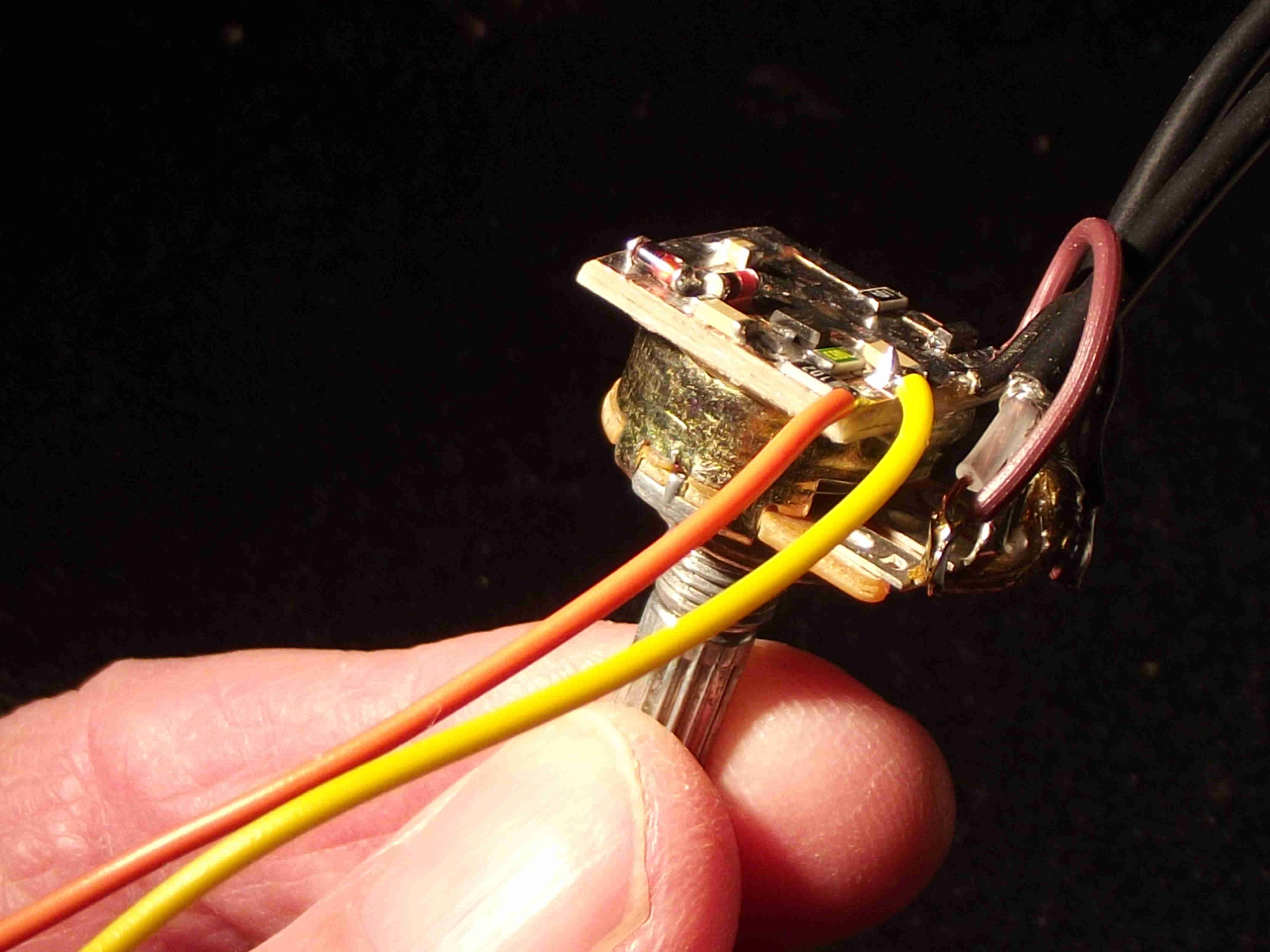
The small board is just the right size to glue on the back of the existing RF gain potentiometer. I wanted to be able switch off the new AGC so I ran 5 volts from the Raduino module through a panel switch to the new board. Reference ground input should be kept short as possible so I ran a 1/2” jumper to the ground side of the potentiometer (which, in turn, is connected to a ground lug surrounding the mounting shaft). The output of the board (labeled “RF” in the sketch) is similarly attached to the other outside lug of the RF gain pot, which is connected to the coax from the receive RF line. Keeping everything short and tidy ensures maximum performance. Finally, a single wire from the “audio in” pad to the high side of the volume control completes the wiring.
The result is similar to the AGC action of the NorCal 40a. An appreciable improvement over other AGC modifications. Still, I believe that the control range could be greatly improved by adding additonal control elements further up the receive chain. The "L" shaped area of the board (where D2, R3, C3 and the gate of Q2 connects) is the connection for these elements. Experimentation needs to be done with an eye on distortion, though. I really enjoy the clean audio quality of the BITX transceivers and would be loath to interfere with that. This is also the point to connect an Raduino analog pin for a better "S" meter. The amplified levels will provide a more accurate low level reading.
A thimble full of parts (OK, maybe half a thimble!) costing a few cents and an evening's fun at the work bench and you will have the basis of several nice improvements. Oh! The RF gain control still works independently, too!
de ND6T