Very few of my home built receivers have internal speakers. They take up a lot of room, they are somewhat fragile, and they seldom sound very good. For these reasons I employ external speakers. The best ones seem to be those sold for mobile radio use. I find an abundance of them at amateur radio swap meets where they appear to have been pulled from the older land mobile replacement programs back when they narrow-banded operation. Most of these are 4” diameter speakers and usually quite efficient. Big magnet structures. They often come with mounting brackets. Compared to the small speakers that most of our store-bought gear uses internally, these speakers are not only more efficient but they sound much better!
I wire the input cord to a 3.5 mm stereo (3 conductor) plug but just wire the tip and the sleeve. Some radios have output jacks that will short if a monoaural (2 conductor) plug is inserted. This will avoid that.
Since I usually use headphones when I operate CW I need headphone jacks, too. My solution is to open the external speaker enclosure and install a headphone jack, and a switch where it can easily be reached. The switch allows me to silence the speaker.
My simple home-made radios often do not include Automatic Gain Control (AGC) so if an extremely strong signal suddenly appears while I have the gain controls up trying to dig out an especially weak signal...WOW! It can get painful.
For decades, the world’s land line telephone systems had a little known feature; A tiny voltage limiter that was wired across the telephone “receiver”. This was transparent to normal audio levels but limited the output levels to less than a volt if there was an accidental ringing voltage or other high level impulse. Millions of telephone sets were thus equipped so this idea is well tested!
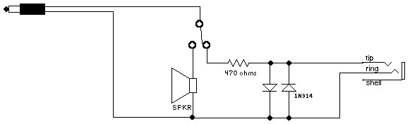
My nice comfortable headphones (Sennheisser HD202) are quite sensitive so I would normally have to reduce my radio gain control adjustments whenever I switched to them. So I included a 470 ohm resistor in series with the audio line on that side of the switch. I follow that resistor with the reverse-parallel silicon switching diodes (most any will work, 1N914, 1N4148, etc.) to shunt any loud signal peaks. No distortion is evident until the signal becomes painful. It does not effect normal level signals. Now I can switch to headphones and my audio levels remain the same from speaker to “cans”. I used a 470 ohm resistor but less sensitive headphones may require something like 100 ohms. Experiment to see what works best for you.
The added jack is wired from tip to ring, the sleeve connection is left disconnected and isolated. That way the monoaural input from the radio is fed through the two headphone transducers in series so that both ears are hearing equally. This also doubles the impedance of the headphone arrangement, allowing the limiting diodes to function efficiently.
If your favorite headphones are wired with a two conductor plug or a larger 1/4’’ plug, just drill another hole and parallel the newly added jack to the first circuit. There is no problem in making it more convenient! That’s just one of the advantages of doing it yourself, you can have it any way you want.
There you have it: Better audio, higher output from those tiny QRP receivers, convenient headphone adapters and safe audio levels, too. A most useful evening project!
de ND6T