Ian Braithwaite's (G4COL) article in SPRAT issue 201 introduced a breakthrough for safely regulating battery voltage. It's an analog design with no RFI and nearly zero drop out voltage. Cheap, simple, and flexible.
In their attempts to use batteries on voltage sensitive equipment like some of the QRPLab's QMX series, some users install series silicon diodes as fixed voltage drops. Others use fixed regulators like the LM7809 or 7812. Some use switch-mode regulators. All of these options suffer from a fixed drop-out voltage that we call "overhead". Unless you are using the high input voltage to power something else, it is inefficient. These usually exhibit around 2 volts of overhead so that when the battery has dropped to 12 volts then you only get 10 volts to the equipment.
A Low Drop Out regulator will get that overhead down to a volt or less. However this Very Low Drop Out circuit improves that to mere millivolts. It provides the selected voltage regardless of the battery supply right up until discharge drops to the selected voltage. Then Q3 is biased on and ceases regulation, providing nearly the same voltage out as is being supplied by the battery. All the way down to below the voltage needed to operate the gear. A smooth and seamless operation. Almost like having the voltage regulator removed as soon as it is unnecessary.
I did some experiments using parts on hand and decreased the quiescent current tenfold. By using an LP2950-5 micropower Low Drop Out regulator for a reference and changing some component values I brought the idle current demand to below 750 microamps throughout the 7 to 20 volt range. The large (but common) PMOS FET is rated at a minimum series resistance ten times lower than the suggested transistor for a bit lower price. Although the rating states 70 amp continuous current keep in mind that it is dependent upon heat sinking capability. The mint tin should be enough for two or three amps.
Values shown in the schematic are for 12 volts. To change the output to 9 volts just replace R4 with a 39K. All resistors can be any size since there is negligible power dissipated. The capacitors need to be able to work at the voltages applied to them so C1 should be rated for at least 20 volts, C2 at least 6 volts, C3 at least 16 volts.
A zener diode was tried as a reference but required much higher current and provided terrible regulation. Even a LM78L05 was tried but it added 3 milliamps drain yet provided good regulation.
My build was originally built on a finned heat sink and when I moved it to a mint-tin enclosure I didn't bother removing it. Ignore the heat sink in the photo: It doesn't help when enclosed. Just bolt Q3 to the tin with appropriate insulation since the transistor is not isolated and the drain is connected to the tab of the TO220 package.
My wife was experimenting with small thermal printers and produced the self adhesive labels for my prototype. Nice having the schematic right in the lid, eh?
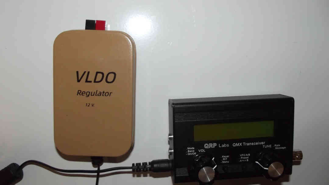
The input jack is mounted in a slot cut in the case, the output cord was salvaged from a defunct power supply wall wart.
de ND6T