I have been enjoying the BITX40 with the AD9850 DDS VFO but when the Raduino was announced I was overwhelmed with curiosity. I ordered a new BITX complete with Raduino. What would I do with another 40 meter BITX? How about 60 meters?
60 meters in the U.S. is pretty limited, currently only 5 fixed channels and limited to 100 watts effective radiated power, and so it is seldom addressed in commercially built gear. It has good propagation for nearby communication and there is a possibility that a new segment (not channels!) will soon be authorized for QRP operation. The BITX would be perfect since it is easy to program for new allocations.
While waiting for the new BITX I considered conversion strategies by using the AADE filter modeling program. First, I modeled the existing 40 meter RF bandpass filter and then modified it for 60 meters. My first idea was to change just the series capacitors in the original. It worked!
The nice curve to the right (in black) is the original RF band pass response. Changing the three series-tuned capacitances produced the response to the left (in red). Yes, it is twice as broad, but that is what I wanted since it would include WWV and a number of frequencies that I enjoy.
The conversion does not require removing any hardware. Just add four common value capacitors! Parallel the three 100 pF capacitors (C2, C4, and C6) in the RF bandpass filter with 100 pF capacitors. I just stacked them. The fourth additional capacitor is a 220 pF capacitor across L7 (in the transmit low-pass network) to attenuate to second harmonic (now > 50 dBc). Voltage ratings are not a problem.
Stacking is done simply if you have some 1206 sized capacitors. Just sweeten the solder fillets on each end of the target capacitors with just a touch of extra solder. Place the additional part atop the target part. Hold it down while re-heating the solder at each end and you will see the capillary action pull the solder up onto the ends to complete the joint. Ta-DA!
No SMD capacitors in your junk box? Just use ceramic disks, then. The 220 pF needs to have leads in order for it to reach across the L7 terminals and it goes underneath the board. You can use a ceramic disk like I did, but a silver mica or any other RF type would work well.
That was too easy. The only thing left to do is to load new operating software and put it on frequency.
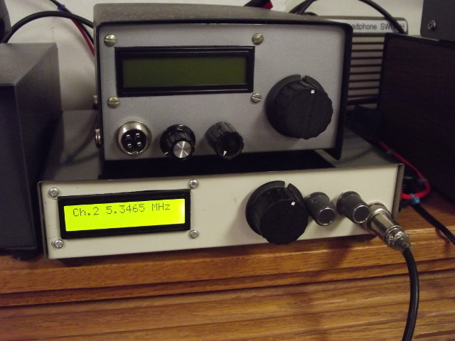
I wrote three operating system “sketches” for the Raduino: The simplest is BITX60.ino. Download the PDF here. No metering. It just steps through the 5 channels currently allocated for the US. The tuning knob is just used as a switch. Turn it clockwise near the end and it starts to step through the channels one step/second. Great for scanning the band for activity. To stop the scan on the selected channel just turn counter-clockwise a bit.
The second sketch (BITX60ST.ino.) is a bit more flexible, allowing tuning all about the 5 MHz band. In addition to the 5 channels you now have channel "zero" which is shuttle tuned. Tune down to 5 MHz for checking time and calibration on WWV, tune up to listen to shortwave broadcasters or to the several trans-oceanic aircraft SSB channels. Careful, transmit is not blocked! Download the PDF here.
The third sketch (ext60.ino) includes S meter, RF power and SWR monitoring, and CW (both straight key and Iambic). This includes the previous two tuning methods, stepped and shuttle-tuned, and includes Voltage-Controlled-Tuning. The latter appears as channel 6 and was done in anticipation that we could join other parts of the world in a frequency agile portion of the spectrum (hopefully with low power restriction). Download the PDF here.
CW in the 5 channels follows FCC mandated 1.5 KHz offset but the VCO tuning is set up for normal operation where offset is the same as the side tone, making spotting easier and allowing more than one CW QSO to occur in a 2.5 KHz space. Use most any linear taper pot for the speed control. Adjust the speed below 10 Words Per Minute to enter straight-key mode. If you want to go faster than 34 WPM, just scale it in the third line of the CW() function but don't forget to change the lines that switch to SK mode just down stream a way. Don't use this software until we get the allocation! It should give you some ideas that you can use elsewhere, though.
To put it right on frequency it would be best to use a frequency counter. This is due to the variations in BFO frequencies and the reference oscillator on the Raduino module. You could do it without equipment by “change and re-try” but a counter (even a borrowed one) would be easier.
This calibration is covered HERE.
I've had one report of insufficient drive resulting from the VFO signal being injected at the original DDS1 jack and being shunted by the C91 and C92 at this higher frequency. That was a poor place to inject the VFO in the first place. A much better choice is the junction of R71, R72, C72, and the base of Q7. You will find that this will reduce some of the "birdies" in the 40m version, too!
See you on 60!
de ND6T